You calibrated the sensor. You matched every strip until the seams disappeared. The relative accuracy report looks clean, every flight line agrees with its neighbor to within a centimeter. Then you check the dataset against a handful of surveyed ground control points, and the whole thing sits eight centimeters off. Nothing about the point cloud looks wrong. It is wrong anyway, and no amount of matching between strips will fix it, because the strips are all consistently wrong together in the same direction.
This is the distinction between relative and absolute accuracy that comes up throughout calibration and strip adjustment, and it points at a layer underneath both of those steps. Calibration removes the sensor’s own angular errors, and matching removes what remains between overlapping strips. Neither one can fix an error in the aircraft’s position and orientation itself, because both steps assume that the trajectory feeding them is correct. If it is not, every point built from it inherits the same mistake. This article looks at what actually determines trajectory quality: the GNSS positioning method, the satellite geometry available during the flight, and the IMU that fills in the gaps between GNSS updates.
What the Trajectory Actually Is
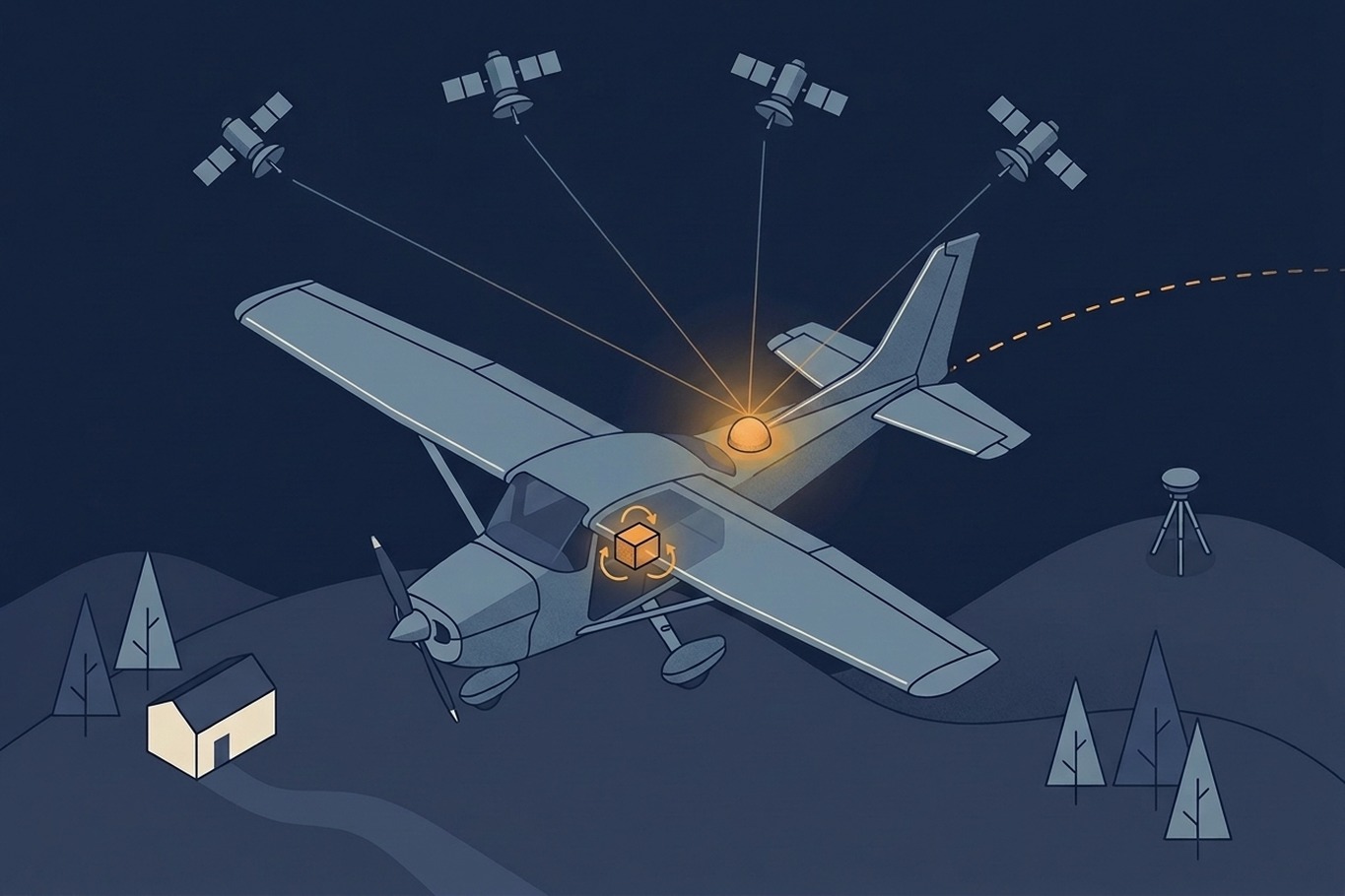
Every LiDAR point starts from a single line: the trajectory, a continuous record of where the aircraft was and how it was oriented at every instant of the flight. GNSS supplies the position part of that record, typically at a rate of a few times per second. The IMU supplies orientation, roll, pitch, and heading, at a much higher rate, often hundreds of times per second, and it also bridges the gaps between GNSS updates by tracking acceleration and rotation in between them.

Neither sensor is trusted alone. A GNSS-only trajectory would be accurate at each update but blind to what happened between updates, and it says nothing about orientation. An IMU-only trajectory would capture orientation and short-term motion well, but its position estimate drifts steadily because it is built by integrating acceleration over time, and small errors accumulate. Processing software fuses the two, using GNSS to anchor absolute position and constrain IMU drift, and using the IMU to interpolate and stabilize between GNSS epochs. The output is a single smoothed trajectory, and it is this trajectory, not the raw sensor logs, that every LiDAR point is ultimately built from.
How Satellite Position Affects GNSS Accuracy
GNSS positioning depends on more than how many satellites are in view. It depends on where they are relative to each other. Satellites clustered together in one part of the sky give a weak geometric fix, because the distance measurements to each of them come from nearly the same direction and constrain the position in almost the same way. Satellites spread widely across the sky give a strong fix, because each one constrains the solution from a different angle. This geometric strength is expressed as dilution of precision, or DOP, with separate values for horizontal accuracy (HDOP), vertical accuracy (VDOP), and the combined position solution (PDOP). A low DOP value means strong geometry and a reliable fix. A high value means the same measurement noise translates into a much larger position error.
Satellite geometry is not constant. It changes continuously as satellites move along their orbits. A flight line planned for a specific time window can fly through a stretch of poor geometry that a line flown an hour earlier or later would have avoided entirely. Terrain and obstructions compound the problem in mountainous or urban survey areas, where valley walls or tall structures block part of the sky and reduce the number of usable satellites regardless of the underlying geometry. Tracking multiple constellations at once, combining GPS with GLONASS, Galileo, and BeiDou, helps directly. More visible satellites generally means a stronger, more resilient geometric solution, even when part of the sky is obstructed.
Further reading
- Understanding GNSS Accuracy Metrics: PDOP, HDOP, and VDOP | gnss.ae
A plain walkthrough of how satellite distribution translates into each DOP value and why mission planning uses PDOP thresholds. - Dilution of Precision (Navigation) | Wikipedia
Background on why clustered versus spread-out satellite geometry produces weak or strong position fixes.
Two Ways to Correct a GNSS Position
A single GNSS receiver on its own, even with a strong satellite geometry, is only accurate to a few meters, because satellite orbit, clock, and atmospheric errors are not fully known in real time. Airborne surveys need centimeter-level accuracy, so those errors have to be corrected, and there are two established ways to do it.
The first is differential correction against a base station at a precisely known position, whether that is a receiver the survey company sets up themselves or a subscription to a Continuously Operating Reference Station (CORS) network. The base station observes the same satellites as the aircraft and logs its own position error. That error is caused mostly by atmospheric conditions the two receivers share, so it can be subtracted from the aircraft’s trajectory during post-processing. How well this works depends on the distance to the base station. The two receivers look through less and less similar atmosphere as they move apart, so the correction weakens gradually instead of failing at a fixed cutoff, typically by one to two centimeters for every ten kilometers of separation. Real-time corrections (RTK), as used on many drones, are therefore usually kept within about 10 to 20 kilometers of the base. Post-processed trajectories for crewed survey aircraft tolerate more, because the software can work through the full recording of both receivers after the flight instead of solving each moment on the spot. The traditional rule of thumb for these is to keep the aircraft within about 30 to 50 kilometers of a base station, and processing against several surrounding CORS stations at once can stretch this considerably further. A survey area larger than that, or one far from any established CORS network, either needs a dedicated base station moved into range or a different correction method entirely.
The second method is Precise Point Positioning, or PPP, which needs no local base station at all. Instead, it applies highly accurate satellite orbit and clock corrections computed from a global network of reference stations, available for any point on Earth. This makes PPP attractive for remote or very large survey areas where setting up or subscribing to local infrastructure is impractical. The trade-off is convergence time. A PPP solution needs the GNSS receiver to observe satellites for an extended, often static, period before it settles into its full accuracy. To achieve this, survey crews start the GNSS system well before takeoff, giving the receiver time to converge while the aircraft is still on the ground. That wait adds to the passive time of a survey flight. There is also a practical delay involved. The most precise orbit and clock products that PPP depends on are not available in real time at their full accuracy, so a PPP-corrected trajectory is typically computed after the fact. The International GNSS Service (IGS) publishes its rapid products about 17 to 41 hours after the observations, and its final products after 12 to 19 days. The rapid products are already close to final accuracy, so a trajectory can usually be processed a day or two after the flight, while projects with the strictest accuracy requirements wait for the final set. That makes PPP a good fit when the project’s delivery timeline can absorb the wait, and a poor fit when results are needed quickly.
For many airborne projects, base station correction remains the default. PPP becomes the practical choice less because of its accuracy and more because of where the survey is, useful specifically where CORS coverage does not reach and where terrain or access makes running a base station of one’s own impractical.
Further reading
- What is Precise Point Positioning (PPP)? | SwiftNav
Compares PPP’s global coverage and convergence time against RTK’s need for nearby base infrastructure. - What is a Vector Baseline? | Point One Navigation
Explains why RTK accuracy is best within about 10 kilometers of a base station and degrades steadily beyond that. - CORSnet-NSW and Airborne LiDAR | Jones et al., NSW Spatial Services
A conference poster showing airborne LiDAR trajectories processed against reference stations up to 600 kilometers away and still matching ground control to within a few centimeters. - PPK vs RTK in Drone Mapping: Complete Guide | DSLRpros
Covers the difference between real-time and post-processed correction, the two most common workflows for airborne GNSS.
How the IMU in Your System Controls Accuracy
GNSS corrections address position, but every LiDAR point also depends on the aircraft’s orientation at the instant the pulse was fired, since a small angular error at survey altitude translates into a much larger error on the ground. This is where the IMU’s own quality becomes a limiting factor separate from GNSS altogether.
IMUs are commonly grouped into tiers, from MEMS-based tactical grade units through fiber-optic navigation and survey grade systems. The key difference between them is how much their orientation and position estimate drifts during the gaps between GNSS updates. Those gaps show up during a turn at the end of a flight line, or during a brief loss of satellite lock. A lower grade MEMS IMU drifts faster and accumulates more error during these gaps, while a fiber-optic gyroscope holds its orientation estimate far more precisely over the same interval, at a higher cost and weight. After post-processing, high-end fiber-optic systems reach roll and pitch accuracy of a few thousandths of a degree, with heading about twice that. Compact MEMS systems built for drones land closer to a few hundredths of a degree for roll and pitch and almost a tenth of a degree for heading. MEMS-based systems typically cannot match those figures without additional support, such as denser GNSS updates or multiple IMUs working together.
The practical impact is that IMU grade should match how often the trajectory will actually rely on it alone. A survey with short flight lines and frequent turns leans on the IMU constantly to bridge each turnaround, so a lower grade unit accumulates drift again and again throughout the mission. A survey with long, steady lines and few turns gives the IMU less work to do between reliable GNSS fixes, so the same lower grade unit performs closer to what a higher grade system would achieve. The choice of IMU is therefore not just a sensor specification. It interacts directly with how the flight itself is planned.
Why Trajectory Quality Is Decided Before Takeoff
The three factors in this article have one thing in common: most of what decides trajectory quality is fixed before the aircraft leaves the ground. The time window of the flight sets the satellite geometry. The choice between a base station and PPP sets how well position errors can be corrected, and how soon. The IMU installed in the aircraft sets how well the trajectory holds up through every turn. Processing can combine these inputs well or poorly, but it cannot add accuracy that the flight never captured.
This also changes what you should ask when you evaluate a dataset. A clean relative accuracy report tells you that the strips agree with each other. It tells you nothing about where the whole block sits. The more revealing questions are which correction method was used, how far the aircraft flew from the nearest base station, whether any lines were flown during stretches of poor PDOP, and what grade of IMU the system carries. A provider who processed the trajectory carefully can answer most of these from the trajectory quality report, which usually shows the estimated position and orientation accuracy along every line of the flight.
Ground control points remain the independent check. They are how the eight-centimeter offset in the opening example came to light, and they are the only way to confirm absolute accuracy against something that did not come from the aircraft itself. How many you need, and where to place them, depends on how much you can trust the trajectory. That makes ground control the natural next question once the trajectory itself is understood.