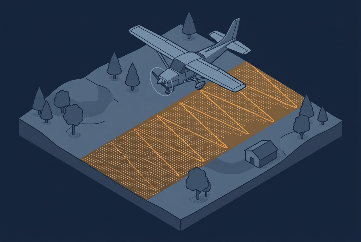
A project specification usually calls out a single number: 8 points per square meter, maybe 20 or even more. That number becomes the thing everyone plans around, quotes against, and checks in QA. Sometimes the spec is written as an average across the project area, sometimes as a minimum that has to be achieved in every part of the project area. What matters here is that either way, the point cloud that actually comes back from a flight is never uniform. Density climbs and falls across the project area, sometimes by a wide margin, even when the reported number technically meets the set requirement.
Several factors drive that variation, and one of the biggest is the scan pattern of the sensor doing the flying. Every lidar sensor steers its laser through space using a specific mechanism, resulting in a distinctive pattern on the ground. Most companies might be familiar with the scan pattern of their sensors. But understanding what pattern your system produces, or which patterns it is capable of generating, is the kind of knowledge that lets you plan your projects better and predict a weak spot in the data before it shows up as a failed QA check.
What Scan Pattern Actually Describes
A lidar sensor builds a point cloud out of two combined motions. One is the platform itself moving forward, whether that is an aircraft, a drone, or a vehicle. The other is the beam being swept laterally across the flight path by some mechanism inside the sensor. That lateral sweep, the shape it traces and the timing behind it, is what “scan pattern” refers to.
It helps to distinguish sensors by their type of scan mechanism. There might be many manufacturers, but all of them rely on mechanisms that have established themselves over the years. What determines the pattern on the ground is the physical way the beam gets deflected, not which company built the housing around it. That is also what determines how density behaves across a swath, which is the thread running through everything below.
Oscillating Mirrors
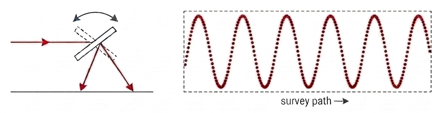
An oscillating mirror was the original approach to steering a lidar beam, and it is still common today. The mirror swings back and forth between two positions, producing the zigzag pattern most people picture when they think of a lidar scan line.
Because the mirror has to decelerate and reaccelerate at each end of its swing, it spends more time near the edges of the pattern than in the middle. More dwell time there combined with a stable pulse repetition frequency means more pulses land in that same stretch of ground, so density actually peaks at the edges of the flight line rather than at nadir. This can be mitigated to some degree by adjusting the pulse repetition frequency as the mirror approaches the turnaround points, thinning the pulse rate there to counteract the extra dwell time and even out the resulting density.
Rotating Polygon Mirrors
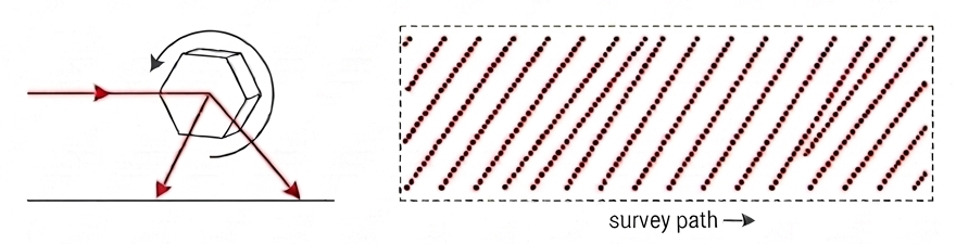
A rotating polygon mirror spins at a constant angular speed, with the laser bouncing off each face in turn as it rotates. The result on the ground is a linear pattern of roughly parallel lines.
Unlike the oscillating mirror, this mechanism does not slow down anywhere, so the pulse rate along the sweep stays constant. What changes is the geometry: near nadir, the beam is nearly perpendicular to the ground, so equal angular steps translate into equal, closely spaced ground distances. Toward the edges of the swath, the beam meets the ground at an increasingly shallow angle, and the same angular step now covers a longer stretch of ground, since the slant range has grown. The result is a pattern that is densest and most even near nadir, thinning out gradually and predictably as you move toward the edges of the swath.
Some designs tilt the individual mirror facets relative to each other. That lets a single revolution of the mirror capture forward, nadir, and backward looks at the same patch of ground, which is useful for scanning vertical surfaces or working through semi-transparent vegetation, since the target gets hit from more than one angle. A single facet tilted at 45 degrees can even produce a full 360 degree panoramic scan.
Conical (Palmer) Scanning
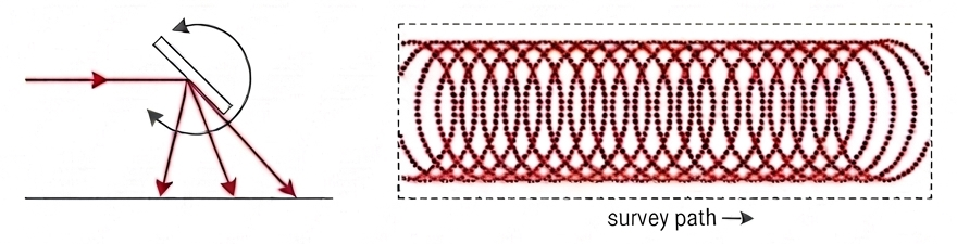
Conical or Palmer scanning steers the beam around a cone rather than back and forth in a plane. On the ground, this traces a series of ellipses rather than lines.
This mechanism shows up mainly in bathymetric lidar, where scanning at an angle helps deal with refraction at the water surface. It is a good example of a scan pattern chosen for physics reasons specific to the application, not for density or coverage reasons at all, which is worth keeping in mind: not every mechanism on this list was optimized for the same goal.
Risley Prisms
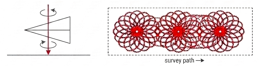
Risley prism systems steer the beam by refraction, shooting through the optical elements rather than reflecting from them. Two glass wedge prisms rotate independently around the same axis, and the pattern traced on the ground depends entirely on how those two prisms rotate relative to each other. Slow, simple ratios between the two rotation speeds produce patterns like straight lines, circles, or spirals. Faster or less regular ratios can produce flower-like petal shapes or figure of eights.
The key advantage of this mechanism is that the relative spin velocity of the two wedges is adjustable. That means a single sensor is not locked into one scan pattern the way a fixed polygon mirror or oscillating mirror is. The same physical unit can be reconfigured to produce different patterns depending on what a project needs, which is a meaningful advantage given how much of a capital investment a sensor represents.
Rotating Multi-Beam Arrays and Solid State
Some sensors skip a dedicated beam steering mechanism altogether and rather send/receive multiple signals simultaneously through a sensor array.
Rotating multi-beam arrays spin an entire bundle of laser transceivers around a shared axis, giving a 360 degree panoramic view, which is a natural fit for narrow streets or valleys where you need returns both above and below the sensor.
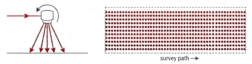
Solid state designs go a step further and remove moving parts entirely, either steering the beam electronically (through MEMS mirrors or micromirrors) or skipping steering altogether in favor of a full detector array that captures a scene the way a camera captures an image (flash lidar).
Density behavior here depends heavily on the specific array or array pattern the manufacturer chose. Where the polygon mirror and oscillating mirror give you a predictable line pattern, an array-based sensor’s density signature is more a function of how many beams are packed into the array and how they are spaced relative to each other.
A Variation in Density Has More Than One Cause
Scan pattern is one contributor to the density variation you see across a project area, but it rarely acts alone. A few other factors compound with it:
Platform motion compresses or stretches scan lines depending on the aircraft’s speed and any roll, pitch, or yaw during the flight. A perfectly even scan pattern from the sensor can still come out uneven on the ground once platform motion is factored in.
Altitude and flight speed change swath geometry directly. Fly higher and the same angular scan pattern spreads over a wider area, thinning density even though the sensor itself has not changed anything about how it sweeps the beam.
None of these factors show up in a single “target density” number. They only become visible once you look at where in the project area the density actually landed.
Working With the Sensor You Have at Hand
Since replacing a sensor for a single project is rarely realistic, the practical move is learning to read the scan pattern you already own well enough to predict where density will run thin before you fly, not after QA flags it.
This matters most in the applications where a sparse patch in the wrong place can fail a deliverable even though the average density across the whole project met spec. Canopy penetration in vegetated terrain depends on getting enough returns through gaps in foliage down to the ground, so a mechanism with uneven pattern density can leave real gaps in ground coverage even at a healthy average. Urban and corridor mapping runs into a related problem: narrow streets and tight corridors concentrate the consequences of a pattern’s blind spots into a small area where they are much more likely to matter.
Even without a new sensor, flight planning gives you some room to compensate for a known pattern weakness. Increasing overlap between flight lines, adjusting altitude, or slowing the platform down can all offset a mechanism’s tendency to thin out in a particular place, once you know where that place is likely to be.
Where This Connects
A target density number is really describing an average or a minimum, and the actual distribution around it depends on the sensor’s scan mechanism as much as it depends on the flight plan built around it. That distinction connects directly back to the four essential LiDAR parameters that get set before any of this: point density itself is one of those four core values, sitting alongside field of view, flightline overlap, and altitude above ground. Each of those four gets planned as a single target number, yet each one plays out unevenly across a project area for its own reasons. Scan pattern is the reason behind point density’s variation specifically.
Once you know which mechanism your sensor uses and how it behaves across a swath, that knowledge feeds directly back into how you plan the other three parameters. A pattern that thins out at the swath edges, for instance, is one more reason to lean toward the higher end of your flightline overlap, so the sparse edge of one strip gets picked up by the denser center of the next. Reading a scan pattern well is less about the mechanism on its own, and more about what it tells you to adjust elsewhere in the mission plan.
Further reading
- Four Essential LiDAR Parameters — tech.rohrba.ch
How point density, field of view, flightline overlap, and altitude above ground interlink during survey planning - Airborne Lidar: A Tutorial for 2025, Part IV — LIDAR Magazine
A current rundown of the beam deflection mechanisms used in UAV lidar, including oscillating mirrors, rotating polygon mirrors, Risley prisms, and solid state designs - LiDAR Sensors, Simplified: Part 1 — AEVEX Aerospace
Background on how point rate depends on scan speed and pulse repetition frequency, comparing raster scan and spinning sensor architectures